best service ,best view
contact us email : 718642093@qq.com
Better service ,Better Design
contact us 718642093@qq.com

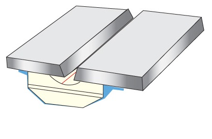
Movement of torch T moves welding wire W along plate A to lay the root pass metal. This movement is provided by a standard robot control mechanism 100, which uses software to perform selected operations and employs real time feedback controls. In accordance with the invention, torch T is moved an arcuate or swinging transverse direction 102 while it is moved a vertical direction 104. Between the swinging action, torch T is moved in the longitudinal direction parallel to ends 14, 16 as indicated by arrows 106. In accordance with the invention, torch T is swung transversely as indicated by arrow 102. During the swinging action, the robotic control mechanism adjusts the vertical height as indicated by arrows 104 so that the vertical height of the torch above backing plate A (ESO) remains constant. Thus, the stick-out is the same as torch T moves along the selected weld path. Control mechanism 100 causes torch T to travel in a preselected pattern or path in laying the root pass over consumable plate A. The selected path is an aspect of the present invention; however, it will be described later since it is not necessary for practicing the broadest aspect of the invention as shown in FIGS. 6-15.
More information: http://www.welding-backing.com/
Date: 2023-04-10 hits: 768 Return
Spot welding ( Ceramic Backing) 2023-04-10
Ultrasonic welding( RIHUI Backing) 2023-04-10
Spot welding( RIHUI Ceramic Welding Backing) 2023-04-10